This page is the Online Teaching Module to responsibly fit and maintain the VGK-S to your client.
Prior to installing the product, please complete the assessment at the bottom of the page. This must be done by each CPO prior to first fitting of a VGK-S. A certification will be returned and must, on demand, be used with warranty or support claim requests.
Table of Contents
- 1 Background
- 2 Lexicon
- 3 Incidence of S-TF amputation
- 4 The Needs of the S-TF amputee
- 5 State-of-the-Art Functions
- 6 Impact of Short Stump
- 6.1 Understanding the real impact of shortness in S-TF amputation
- 6.2 Understanding the impact of the Moment of Inertia
- 6.3 Different demands of Spine vs Stump
- 6.4 Moment of Inertia as a worked example
- 6.5 The meaning of Moment of Inertia and Forces in and on the Skin
- 6.6 Proprioception in relation to skin stimulus
- 6.7 Influence of actual Wrapped Femoral Length
- 7 The Stumble
- 8 Alignment
1 Background
1.1 About this manual
This long manual is provides useful insight in understanding issues, risks and treatment advantages with regards to the prosthetic management of short transfemoral stump and hip-disarticulation. The manual cannot be shortened in lieu of gaining better understanding: Orthomobility ask you to bear with us and join in the revolution of better amputee care.
To assist the reader, the essentials are from written in blue to allow some speed reading, and the additional explanations are written in grey where these are good but not essential to read. Other relevant text is in black. The highlights are to assist familiarisation with the concepts, but the whole of the text is meant to be read and understood for best practice.
The essential theory must be read and understood to safely install the VGK-S. It is the responsibility of the installing / prescribing CPO to have read and understood this manual.
1.2 Technology
The VGK-S is a Fluidic Processor Knee with a unique approach. The knee has been designed for transfemoral amputees with short transfemoral amputation (S-TF) and hip disarticulation (HD) to reduce some medical problems normally associated by shortness of stump.
FPKs are prosthetic knees that use fluidic sensors to respond to changes in gait in real-time, by adjusting motion resistance within a single step. Click here to learn more about the FPK technology.
2 Lexicon
STUMP
From “A Manual for Above-Knee Amputees”: “In recent years, there has arisen an aversion to the use of the word “stump” in referring to that part of the limb that is left after amputation, and attempts have been made to find another term has proven to a difficult task, because there is no synonym in the English language for “stump”, and the word “stump” has been retained by the International Standards Organization and is used here to avoid confusion”.
MOI
Moment of Inertia (MOI), a measure used in mechanics/physics to quantify the effect that that the force required to move a mass at a distance is proportional to the square of the distance.
MOI = mass x distance^2
FLEXION
The movement in the in swing when the knee bends.
EXTENSION
The movement when the knee straightens out
YIELDING
The bending of the knee under body weight.
FREE MODE
The low resistance bending of the knee in the cycling mode.
S-TF (SHORT-TRANSFERMORAL)
Short Transfemoral is a proposed new classification of amputation length, where the meaning is different in accordance to the take on it. Medically, a S-TF amputation usually means that the stump is less than 1/3rd of the original femoral length. The VGK-S can be fitted if there is 20 cm between the contralateral patella to the end of the stump.
WFL
Wrapped Femoral Length, a word to indicate a level of functional connection between residual bone length and connection to the socket. The socket design may affect how long the effective length of the bone is when compared between two socket designs.
3 Incidence of S-TF amputation
Short Transfemoral amputation is the post-surgical outcome for a significant number of amputees, often followed with difficulties with prosthetic care. The actual incidence of Short Transfemoral Amputation (S-TF) is not well reported. S-TF amputation is believed to affect younger people more, due to trauma and tumours being main causes for S-TF amputation.
4 The Needs of the S-TF amputee
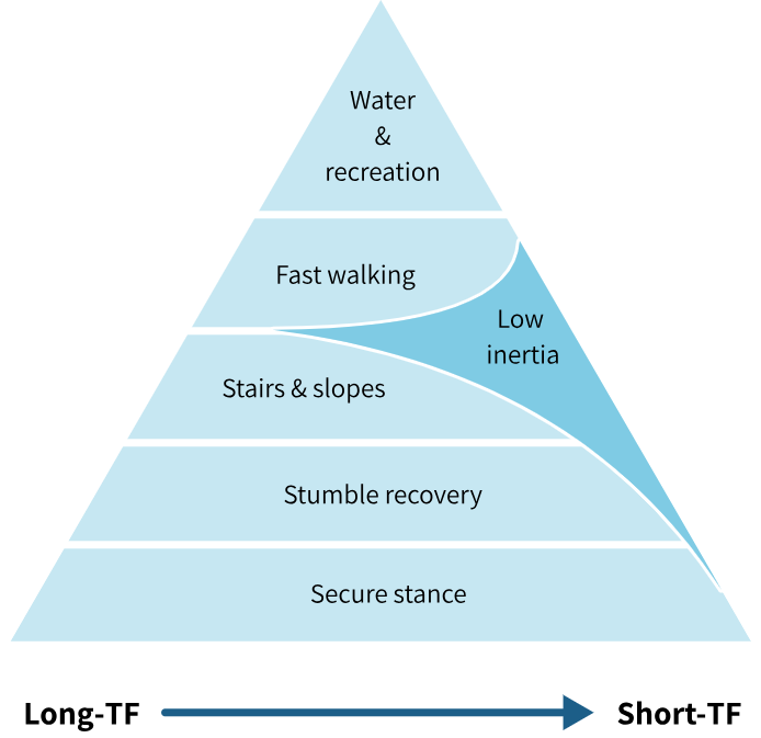
Orthomobility has devised an easy way to visualise hierarchy of needs of the transfemoral amputee, in a way patterned after Abraham Maslow’s hierarchy of needs. There are many different knee joint designs, each with their own characteristics, so it’s important to have a method to assess what they can individually do.
Modern knee joints, both fluidic and electronic, show that the provision of secure stance and swing functions can significantly improve post-amputation mobility.
- The hierarchy shows that a secure stance is of prime importance and closely followed by confidence in a stumble recovery.
- After provision of stumble recovery, stairs and slope descent adds to functional movement. Some amputees may ‘free fall’ down the stairs by allowing the knee to buckle, but this doesn’t remove the requirement for controlled stair and slope descent. This is because the ability to free fall will only last until the ‘sound’ ankle and knee are worn out from over-use.
- Once the stance phase is secure, the amputee can confidently try walking at variable cadence, permitted by a controlled swing phase by the knee joint.
- On top of the triangle are the more recreational and often overlooked aspects of using a prosthesis, and a catch all for the odd, infrequent kind of movements.
The need of low inertia becomes more significant with a S-TF amputation, due to increased reaction forces in the soft tissues with a short stump. Orthomobility believes that the need for low inertia at some point becomes more important than other functionalities in the hierarchy, because it improves the length of time that the amputee can wear the prosthesis with (relative) comfort.
5 State-of-the-Art Functions
A modern knee joint features secure stance phase, stumble recovery adaptive response to cadence. Unfortunately functionality tends to add mass to the knee. The design of the VGK-S minimises mass and due to the location of knee joint in the prosthesis, minimises the Moment of Inertia as well. The impact of a low MOI will be explained in a later section.
There point to two major theoretical aspects to VGK-S that needs to be understood to fully employ the advantages of VGK-S over knee joints with centre of mass distal to the knee axis:
- Importance of small Moment of Inertia.
- Interruptible swing phase by hip extension.
6 Impact of Short Stump
6.1 Understanding the real impact of shortness in S-TF amputation
A short stump means that all the muscles have been cut shorter, and the distribution of muscle power between the muscles is different, and that the length over which the muscles can contract with power is likely to be reduced, and the total muscle volume to produce energy is reduced.
Transfemoral amputees need a knee joint to provide stance phase control (high resistance to support body-weight bearing,) and swing phase control (low resistance to facilitate swing through). In walking, the amputee needs to control the prosthesis with the residual femur and the controlling muscles. Short stump causes reduced contact area within the socket causing elevated contact pressures. From basic mechanical considerations it can be reasoned that the net energy that is required to kick a prosthesis forward in swing, and to reabsorb this energy in terminal swing is roughly the same for those with short and long transfemoral amputation stumps (for a given walking speed). Let this be called Net Swing Energy. The gross energy required to move a prosthesis, is believed to increase with diminishing stump length due to increase in compensatory movements for which the human body is not optimised.
6.2 Understanding the impact of the Moment of Inertia
From the considerations in Section 6.1, any reduction in mass of the prosthesis will reduce the Net Swing Energy required to move the prosthesis through swing, as will a reduction of walking speed. When prosthetic movement is not well attuned to the overall balance of the body, more complicated compensatory movements are required.
Any reduction in the Second Moment of Inertia of the prosthesis will reduce the forces on the amputation stump when swinging the limb through.
‘Moment of Inertia’ can be explained as that for ANY given bit of MASS that is moved at a DISTANCE (e.g. a foot at its distance from the hip joint, say 85 cm), the force required is proportional to the SQUARE of the distance of that given mass. Please refer to Figure 6(c), a Centre of Mass is located at a distance from a pivoting point, about which this mass is moved into swing. In the figure the ‘pivot’ point is chosen to be mid depth of the socket, to take into account that the femur-socket interface is effectively a joint in itself. Taking the Greater Trochanter as the reference point for discussing the effects of inertia would be similarly valid, as that is the point about which the muscles act.

The centre of mass of the prosthesis is the contribution from the foot and the contribution from the knee (and the other components). The location of the mass affects the Moment of Inertia. In other words, if the distance of the foot to the hip were halved (i.e. ½), the force required to move it the same step length would be ¼, this, naturally is not possible.
However, the location of the centre of mass of the knee joint can be redesigned.
To bring the same theory alive, you can imagine the difference in feel of holding a heavy hammer close to its head vs at the end of its handle. Holding the hammer close to its head (the heavy part) will make it easier to move.
6.3 Different demands of Spine vs Stump
The mass of the prosthesis, and especially the inertial properties of the prosthesis are deemed to affect gait in two opposing ways:
- The spine and its musculature need a prosthesis that feels like the contralateral limb. This means similarities in mass, damping and energy production and absorption.
- However the stump must move the prosthesis, and that places limitations on the amount of force that can be delivered. The stump requires to the contrary, a light, low-inertia limb.
Whereas this may sound contradictory, it makes sense from the ‘perspective of the hip joint’. The natural leg feels light during toe-off, (because the calf muscles fire the shin into movement, without involving the hip muscles too much moving this inertia), whereas prior to heel strike, the powerful Glutei decelerate the impulse in the leg, and work against the full inertia of the limb. The user of a prosthesis has lost the push off power of the calf muscles, and therefore the hip must assume both roles, hence the apparent contradictory requirements.
In the S-TF amputee the low Moment of Inertia is of overbearing importance. Low Moment of Inertia of the prosthesis means an improved relationship between stump position and limb position, since the reactive forces are diminished, and passive tissue deformation against a backdrop of unavoidable tissue compliance will be reduced.
Gain of proprioceptive awareness contributes to safety and wellbeing.
6.4 Moment of Inertia as a worked example
Why a worked example? This gives some ideas how user feedback relates to your prosthesis design / prescription.
The prosthesis can be thought of as consisting of the foot, the knee and the socket. Here the adapters and tubes are ignored for brevity. Each of these components has a location.
Force is required to move all elements through swing. There are means to make estimations of those forces, and gain understanding of the influence of the different parts of the prosthesis on the overall experience of the prosthesis in relation to stump length.
The following reflection uses some theory from mechanics, where it is postulated that the movement of an object with mass m around distance d to a point, requires a force (strictly speaking a moment) M. The relationship between these is M = m x d2. This is the situation of the hip joint moving a distance (=d) prosthesis (=m) through swing (=around a point, e.g. the hip). It is worth following the simple calculations below to appreciate the relative contributions of the foot, knee, and socket. Figure 6(d) shows two artistic renderings of an artificial limb, one with a Traditional location of mass of knee joint on the left side, and one with a State-of-the-Art proximal location of mass of knee joint on the right side, that is above the knee axis.
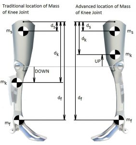
With some simple estimating calculations, a picture can be gathered about the impact of shifting the centre of mass mk of the knee joint. (The figures are made up for the purposes of the worked example, and some lesser second order rotation effects are ignored).
The foot with an estimated mass mf of say 600 gr, can only be located far away at fixed, user specific, distance df =0.9 m from the hip joint (greater trochanter as reference) to accommodate the full limb length. There is no possible alternative to its location. The distance of this mass contributes to the Moment of Inertia of the prosthesis in squared proportion to its mass. A refinement of theory will indicate that the delay in swing movement of the foot will cause a smoothening out of acceleration and diminish the inertial effect a little. However and whatever the inertial effect is, it is a relatively fixed given value for that walking speed, for any kind of better knee joint. Other than diminishing mass of foot and shoe, there is little that can be done with the distance of the foot to reduce the MOI of the foot. Estimate the MOIfoot at 50% x .6 x .92 = .27 * kgm2, where the estimated 50% accounts for the smoothening out of the acceleration of the foot due to double pendulum action.
The user specific- socket with an estimated mass ms of say 1000 gr is surrounding the stump and its close proximity to the stump ds = 0.1 m from hip makes it MOI very small indeed. Estimate the MOIsocket at 1 x .12 = .01 kgm2.
The functional knee with an estimated mass mk of say 1350 gr can be located traditionally at (e.g.) 0. 46 m from the hip makes an estimated SMItraditional_knee at 1.35 x .462 = .28 kgm2. Traditional means in this case, ‘distal to the knee centre’. A VGK-S with an estimated mass mk of 1000 gr can be equivalently located at dk = 0.34 mm from the hip, making an estimated MOIVGK-S_knee at 1 x .342 = 0.12 kgm2.
| (using Greater Trochanter as reference) | Traditional prosthesis (kgm2) | VGK-S prosthesis (kgm2) |
| Foot | 0.19 | 0.19 |
| Knee | 0.28 | 0.12 |
| Socket | 0.01 | 0.01 |
| Total | 0.48 | 0.32 -> a saving of 40% |
This is, despite any margins of error in estimations, a strong indication that the experience of a lighter limb has a basis in engineering prediction.
6.5 The meaning of Moment of Inertia and Forces in and on the Skin
The femur is moved by the muscles about the hip joint. The innervation in the joint capsules and muscle fibres and skin about the amputation stump provide proprioceptive feedback (proprioception is spatial awareness of body parts).
After donning a socket, the skin in contact with the socket is relatively fixed (unless it rubs or slides), and the skin just outside the socket needs to stretch more than normal to allow socket movement relative to the pelvis. Naturally, the socket does not move exactly the same as the femur, due to resistance of skin stretch, and soft compliance of muscle and fat tissue between socket wall and femur. With small movements and low restriction of socket movement the relationship, that is the Femur-Socket Coupling will be good, but if the socket is restrained then the femur moves and the socket does not, and then the Femur-Socket Coupling is badly affected.
During the swing phase of the prosthesis, the MOI dynamically restrains the movement of the socket, and therefore deteriorates the Femur-Socket Coupling. It follows naturally that a lower MOI improves the Femur-Socket Coupling.
The brain is able ‘to feel’ in the distance through objects connected or held by the body, e.g. use of cutlery, walking sticks, spades, and even sockets and prosthesis. As the next paragraph will consider, the ability to accurately feel at a distance through objects (like the socket and prosthesis as a whole) is dependent on the force levels involved.
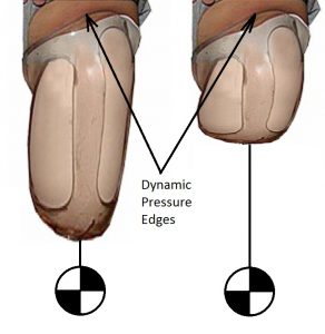
Figure 6(e) illustrates the bulging of the flesh over the socket edge, and when the socket is fixed to a mass with an inertia, the pressure ‘edge’ becomes dynamic: the shorter the stump, the more forceful and dynamic these pressure edges become, and this decreases the proprioception of the prosthesis.
6.6 Proprioception in relation to skin stimulus
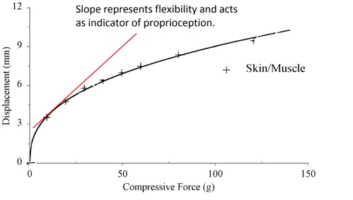
When inertial forces, cause skin displacement, (such as the bulges in Figure 6(e)), a relationship between force and deformation is highly non-linear, and such a relationship can be illustrated from experimental results.
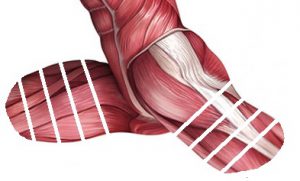
A study, into the compliance of skin overlying muscle and fat tissues in rat, see also adjacent figure,
shows that with low forces the displacement of skin is disproportional to the force applied, whereas at higher forces the displacement of skin is less than proportional to the force applied.
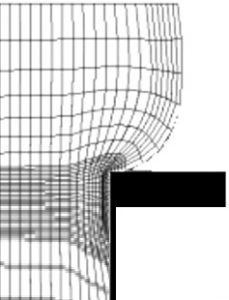
The ‘Deformed mesh’ of the finite element model 6.g illustrates skin tension about a socket edge (black).
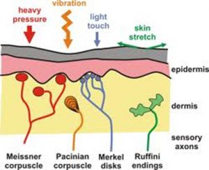
Within the skin there are Ruffini nerve endings as shown that are Encapsulated Collagen type, sense Touch & Skin Stretch and signal Direction & Force. ‘The Ruffini corpuscle, which is located in the connective tissue of the dermis, is a relatively large spindle shaped structure tied into the local collagen matrix. It is, in this way, similar to the Golgi tendon organ in muscle. Its association with connective tissue makes it selectively sensitive to skin stretch’.
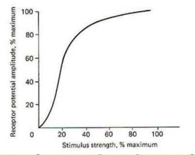
The neural response to mechanical response can be illustrated as per adjacent figure, where it shows that the best discrimination of the nerve cells is in the low stimulus region: where the curve is most vertical, the largest change in receptor potential (=nerve ending response) for the minimum change in stimulus strength (=further skin stretch). When combined with the earlier information of skin deformation vs force, the best ability to feel is when the skin is close to neutral in deformation, and when force levels are low. To the contrary, and in case of high force, when the skin is taut, and resists further deformation, the neural response also flattens out.
These are indicators that reduction in the MOI of the prosthesis supports improved proprioceptive awareness by reducing the range of tissue deformation throughout swing (when inertia dominates the forces), and thereby improving the relationship between neural response to skin stretch, and hence improve sensation of ‘direction and force’, which by reason and experience supports proprioceptive awareness.
This means that for the S-TF amputee, low MOI has an objective medical impact, as opposed to a possible perceived limited scope such as ‘subjective’ improved comfort.
6.7 Influence of actual Wrapped Femoral Length
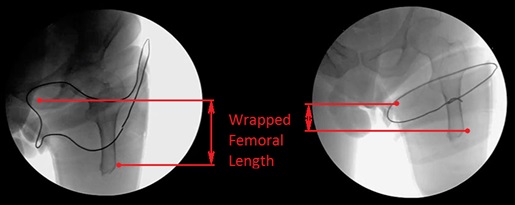
Whereas the VGK-S allows the significant lowering of the MOI of the prosthesis, relative to the hip joint, the results may not be the same for the even shorter S-TF amputation stumps. The Femur-Socket-coupling becomes inversely proportionally poor with further shortening of bone length.
A new useful measure would be to maximise the length of femoral bone wrapped by the socket. Let this measure be ‘wrapped femoral length’ WFL.
The X-ray figure shows the positive influence a good socket design can have on the Wrapped Femoral Length, but also how poor the relationship can be between Wrapped Femoral Length and socket diameter. As per the x-ray photo, the reaction forces in the 6 cm WFL will be double of those in a 12 cm Wrapped Femoral Length, in other words, available bone length to be contained in the socket is critical for resulting force levels. By walking slower, the amputee can reduce the Inertial forces and in that sense control comfort and proprioceptive awareness.
7 The Stumble
The stumble is a brief moment of interrupted swing phase, and is poorly understood in terms of general perception. For improving amputee care it is helpful to review this event.
Shirota et al. have conducted a very extensive study on the subject of tripping. Their results indicate “that it is also important to implement adequate responses when the prosthesis is the support limb, as its ability to coordinate with the tripped leg greatly influences how subjects recover balance” (Shirota, Simon and Kuiken, 2015). They also provide an excellent illustrating film to illustrate a variety of recovery strategies.
The ‘stumble’ is the situation when the prosthetic foot during swing extension hits the ground. The prosthetic foot cannot move and the forward momentum in the trunk cannot be immediately stopped.
The forward momentum of the foot and shin is split between an impact force to the ground and an impact force that travels to the socket into the amputation stump.
7.1 The Crossed Extensor Reflex
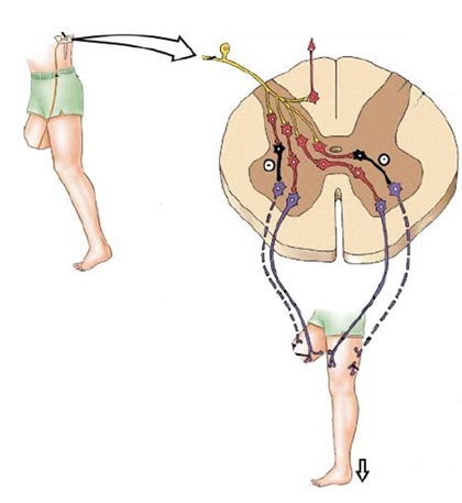
Whilst the body reflexes act, the stumbling limb is the limb that must take the body weight, and here the Crossed Extensor Reflex is understood to be triggered. Normally this reflex is explained as being a withdrawal reflex, such as when stepping on a painful stimulus. However, in case of the stumble the situation is more complex because of the momentum involved in walking. The crossed extensor reflex works the other way round: the stumbling limb with its forward momentum causes a knee flexion and a knee extensor stretch, not dissimilar to the hammer the doctor uses to test for knee tendon reflex. The knee extensors trigger, and so do the hip extensors, and by crossed extensor reflex the hip flexors and knee flexors in the contralateral limb (that is in stance phase!), initiate a rapid swing mode, that in concert with arm movements and forward bending of the trunk allow a rapid forward movement of the contralateral limb to prepare for weight acceptance, so that the tripping limb can be brought out of hazard zone.
7.2 Crossed Extensor Reflex, in the Stumble-Recovering Amputee
For the amputee, the tripping prosthesis itself cannot fire off a knee extensor reflex, and that is where a default stance knee joint normally adds so much safety to the amputee: the knee is ready to give high resistance, as if there were a knee extensor reflex.
In the event of a stumble, the presence of similar sequences of body postures, is seen in:
- a person with two biological legs
- an amputee with a default stance knee joint,
- an amputee with the VGK-S
This suggests that a Crossed Extensor Reflex is at work, because the time to consciously produce those movements is simply too short.
7.4 Stumble Recovery by Interrupting Swing Phase
Note that the information in the following section is also available in the VGK-S Instructions for Use.
Hip extension is the trigger for the VGK-S to adopt high resistance to knee flexion, as well as hip flexion resistance under a flexing knee. The spinal reflexes create a hip extension moment during a stumble, which forms the basis of an expectation of stumble recovery support in the VGK-S.
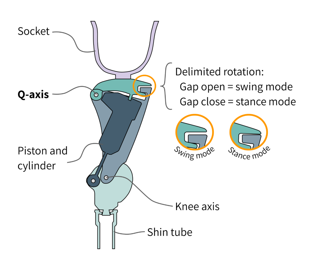
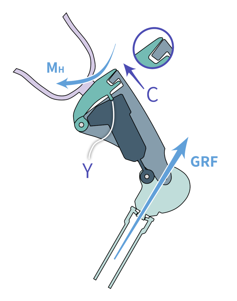
Figure 7(b) shows the presence of a ‘gap’ that allows a small movement about the Q-axis, which controls a valve that can block the swing mode. When the prosthesis is in swing mode, and is pulled forward, the Gap is maximum, and the swing valve is ‘opened’.
A more detailed explanation: When weight or hip extension is applied onto the prosthesis, the socket and body weight press down on the Gap, and it closes, such as to block the swing mode. When the limb is lifted off by weight relief and hip flexion, this Gap opens as far as possible, and permits the swing mode. This is the basic mode of operation. The movement of this Gap must not be blocked.
If the hip is extended, like the application of hip extension moment MH in Figure 7(c) , and the foot is restrained one way or another (and returns a Ground Reaction Force GRF in Figure 7(c)), the same Gap will close with a closing movement C in and engages the Yield Function Y, which is the high resistance. You may notice that upon the initiation of the high resistance to bending Y, the socket will now ‘fall off’ about the Q-axis, and cause a reversal of movement C, and should disengage the yielding resistance Y. This is however not the case, because an internal memory retains the state of high resistance despite the removal of the resistance-triggering movement C. In this way, the combination of the hip extensor reflex in the presence of an interrupted swing switching the VGK-S to high resistance mode, and the internal memory systems maintaining this state of high resistance, makes Stumble Recovery Support a reality.
7.4 What is NOT a stumble?
It has been observed that in walking downstairs on heel strike with incomplete extension, the stance phase does not automatically trigger. In this situation BOTH hips are flexing:
- the sound hip is flexing in the usual way during descent, and
- the limb-wearing hip is set to flex.
If the hip is not pushed into extension, the knee may operate in SWING mode, and may be experienced as not giving resistance to stair descent.
In this situation where the Crossed Extensor Reflex is not fired, the amputee needs to learn to either place the foot and knee better, OR learn to press the VGK-S into high resistance mode as part of the descent strategy.
Please understand this event is NOT a ‘stumble’ since it does not involve a premature stopping of knee extension, and therefor is not likely to trigger the Crossed Extensor Reflex. Instead call it a ‘fold’.
Please teach and train the user the correct stairs descent.

8 Alignment
Note that full alignment instructions are available in the VGK-S Instructions for Use. All the information in the Instructions for Use is considered to be part of the VGK-S online course. Please also study the Instructions for use before completing the assessment.
8.1 The Q-line
The VGK-S uses the principle of a hip-knee-ankle (HKA) alignment system, where the knee centre is ideally a minimum of 10 mm posterior to the Hip Ankle line. There are known cases where the user wants a more dynamic set-up, and that is permissible in agreement with the CPO. The VGK-S has a proximal pyramid receiver and a distal male pyramid. This allows for some mechanical alignment changes that affect the switching behaviour of the VGK-S.
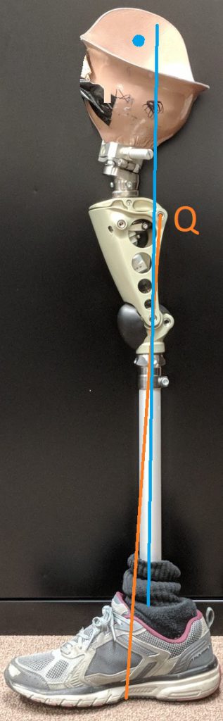
When a line is drawn through the proximal posterior axis (the ‘Q-axis’ in Figure 8(a)) and the main knee axis, this line (the Q-line) will intersect the foot between ankle and forefoot, indicated as Qm in Figure 8(a), with ‘m’ referring to ‘midfoot’.
This location determines that any ground reaction vector entering the foot posterior to Qm has the possibility to pass posterior to the knee axis, causing a knee flexion moment. This will cause the knee to bend. If this ground reaction force passes anterior to the Q-axis, the ‘gap’ (see Figure 7(c)) closes and the high resistance mode is immediately activated, so that this bending occurs under high resistance.
Should the ground reaction force pass posterior to the Q-axis as well, then no high resistance will initially be activated and the socket will flex about both the knee and the hip. Because the socket is wrapped around the residual limb, this socket flexion about the hip is resisted by the residual limb and this resistance will belatedly trigger the high resistance function, and a high resistance flexion is expected.
If the residual femur is extremely short, then the effectiveness of this belated control (interruptible swing) will be diminished. Note: Such belated control is impossible in conventional weight activated knee joints.
When a GRF passes anterior to the knee axis, the knee is naturally stable.
When a GRF passes posterior to the knee axis AND posterior to the Q-axis, the knee is forced into flexion, and, due to the relatively minor displacement of the top pyramid receiving thigh plate moving away from the main frame, the hydraulic unit is in low flexion resistance to support swing.
The Q-line can be made to intersect the sole of the foot at different locations through changes in alignment. When this intersection is more posterior than location Qm in Figure 8(a) (this is achieved by the knee tilting forward over the shin), then the safety (in relation to accidental or intended midfoot-strike) is reduced, and requires more corrective hip effort.
When this intersection is placed more anteriorly to location Qm in Figure 8(a), the safety increases (knee tilting back over the shin), but at a potential cost of making swing release more deliberate, since there will be less forefoot area available to functionally transmit the GRF. This set-up can be used with those users who lift their limb prior to swing initiation and want maximum safety.
A proximal VGK-S perpendicular to the shin tube delivers normally the best results (the top flat of the VGK-S being horizontal).
In planning for the safety and ease of operation, the Q-line must be set-up first.
8.2 Alignment Case Studies
In this case study, there were problems with retrofitting a socket. The example below shows a case where the retrofit required the socket to be shifted forward at the expense of the Q line cutting through the midfoot.
In this set-up the user experienced reduced stability, even though the “interruptible swing” continued to work. The reduced stability is inline with the theory in Section 8.1.
It is recommended to bear the correct Q-angle in mind at all times.
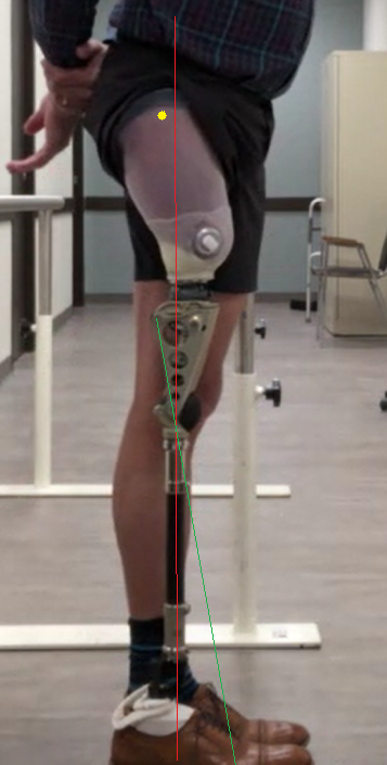
A case was identified where the VGK-S was not ‘releasing’ into swing. Taking a lateral view is a very handy tool to ascertain the cause.
First, it was noted that lever Lf is in the up-position (see VGK-S Instructions for Use for explanation of the controls), and therefore will block the normal swing phase. The lever may be unintended in this position and cause the apparent non-releasing of the knee. The knee joint itself was working as intended.
After rectifying the lever setting, the user still had some problems. The problem becomes clear in the lateral view, with the Q-line and ideal weight line drawn on the picture.
- The Q-line connects the Q-axis with the knee centre and projects this line onto the foot (see VGK-S Instructions for Use for further explanation)
- The “ideal weight line” is a vertical line drawn 10 mm in front of the knee centre.
From the lateral view, the Q-lines was already set up correctly, such that the knee joint was not tilted too far forwards or backwards. However the Greater Trochanter (marked in yellow) was located behind the ideal weight line (marked in red). This brings the ground reaction force closer to the Q-line and makes the ‘operating signal’ less efficient.
References
Shirota, C., Simon, A.M. & Kuiken, T.A. Transfemoral amputee recovery strategies following trips to their sound and prosthesis sides throughout swing phase. J NeuroEngineering Rehabil 12, 79 (2015). https://doi.org/10.1186/s12984-015-0067-8